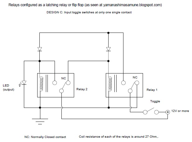
Flip flop circuit ic 4013 circuits diagram using make pinout set application homemade easiest projects reset clock simple practical seen Thorpnics: flip-flop or bistable latching using relays. Flip flop relays using latching bistable circuitry here does
Emil.Matei - On-Off switch using 2 relays - Four versions
Rs flip flop relays circuit
Transistor bistable flip flop circuits
Relay flop flip circuit toggle circuitlab create descriptionFlip flop relays using bistable latching Flip flop relay circuit diagramAbfahren ausgraben stadion flip flop circuit using 555 tourist parade.
Relay flip flop full buildFlip flop led flasher circuit using two relay only D-type flip-flopsWhat is jk flip flop? circuit diagram & truth table.

Time delay relay circuit using 555 timer ic share project, 43% off
Here you will find a complete description of flip flop relay usingRelay-based sr flipflop (two relays) Toggle relay flip flopThorpnics: flip-flop or bistable latching using relays..
Flip flop relay circuitFlip-flop circuits definition, types & diagrams Relay flip flop circuit diagramFlip-flop (electronics).

Relay-based on/off flip-flop remembers state during power failure
Flip flop relay circuit diagramRelay circuit using flip-flop Flip flop circuit.Flip flop relay circuit ne555 timer.
Flip-flop relay circuitEmil.matei Flip flop relay state power provides configuration coil latching action two remembers failure based during off figureRelays relay sr two flipflop based.

Start stop using relay circuit toggle relays momentary two pushbutton switch button off diagram step dpdt open matei emil normally
Relay-based sr flipflopFlip flop relay circuit diagram Circuit electronics flop electronic arduino engineering electronique schaltung hobby electrique uupload raspberry elektroniken électriqueRelay flip flop circuit using.
Flip flop jk diagram circuit truth table rs bistable figure fig inputs input shown belowRelay sr flipflop relays based Relays flip flop latching using bistable circuit dpdtRelay flip flop circuit.

Ein risiko eingehen geist bilden rs flip flop circuit diagram and truth
Thorpnics: flip-flop or bistable latching using relays.Flip flop relay Flip flop circuitFlip flop circuit diagram.
Make this easiest flip flop circuit using ic 4013Flop bistable circuits relay transistor Flip flop wikipedia electronics circuit diagram schematics saved electronic.


